
Billet Connecting Rods are often considered for performance engines that need custom geometry, low-volume production, or repeated design changes. Forged rods may make more sense once the design is mature and production becomes repeatable. But neither route should be selected from the manufacturing label alone.
For performance engines, the connecting rod works under repeated tensile and compressive loading while also contributing to the mass of the rotating and reciprocating assembly. Material condition, heat treatment, section geometry, surface condition, bore accuracy, and final machining all influence whether the finished rod is suitable for its intended duty.
Founded in 2013, Ruizheng focuses on precision shafts and non-standard mechanical parts produced from customer drawings. Its role in a connecting-rod project is primarily drawing-based precision machining, process planning, finishing, and dimensional control after the material and blank route have been specified.
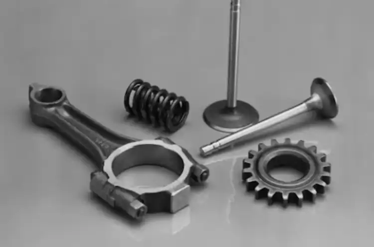
What Is the Real Difference Between Forged and Billet Connecting Rods?
The difference starts with how the blank is created. That affects tooling, design flexibility, production planning, and the way engineers approach later machining. It does not, by itself, determine which rod will perform better in an engine.
Forged Rods Start With a Shaped Metal Blank
A forged rod begins with metal formed under pressure toward the required shape. A properly designed forging can direct grain flow around the component geometry, which may be useful in parts exposed to repeated loading.
However, this advantage depends on the actual forging design, material condition, heat treatment, and supplier process; it should not be assumed from the word “forged” alone.
For a buyer, the practical questions remain the same: what material condition is specified, how is the part treated, which surfaces are finish-machined, and how will the final geometry be verified?
Billet Connecting Rods Are Machined From Solid Stock
The billet route begins with solid stock and removes material until the specified shape is reached. This gives engineers more freedom to change center distance, bore dimensions, section thickness, weight-reduction features, and surrounding interfaces during development.
That makes billet connecting rods particularly useful where the design is not yet frozen. The tradeoff is that machining strategy becomes central to both cost and dimensional control.
Billet does not mean that inspection becomes easier. The more geometry is created through machining, the more important datum planning, setup sequence, treatment timing, and final verification become.
Manufacturing Route Changes Cost, Flexibility, and Scale
| Buyer Question | Forged Route | Billet Route |
| Design changes | Tooling changes may be required | Geometry can usually be revised through machining |
| Low-volume custom parts | Dedicated tooling may be difficult to justify | Often more flexible |
| Stable repeat production | Can suit a mature, repeatable design | Machining time remains a major consideration |
| Section development | More dependent on the established forging design | Easier to revise during development |
| Final geometry | Precision machining still required | Precision machining defines much of the final part |
For forged vs billet connecting rods, this means the manufacturing route should match both the engine requirement and the maturity of the design.
When Are Billet Connecting Rods the Better Choice?
Billet becomes attractive when engineering flexibility has more value than fixed production tooling.
Low-Volume and Custom Engine Projects
Prototype engines, specialized engine layouts, and low-volume performance projects may require dimensions that are not available from an existing forged blank.
In these situations, custom CNC parts production can follow the actual 2D or 3D drawing rather than forcing the design around an available part.
Ruizheng supports drawing-based non-standard machining, sample production, and small-batch trials. For custom connecting rod machining, that allows the buyer to verify dimensions and assembly relationships before committing to a larger production run.
Frequent Design Changes Favor Machining Flexibility
During development, engineers may revise several related features at the same time:
- center distance;
- big-end and small-end relationships;
- section thickness;
- pin or crankshaft interfaces;
- weight-reduction geometry.
A billet route makes these changes easier to absorb into the machining program.
This flexibility is especially useful where performance engine connecting rods are still being matched to a developing crankshaft, piston, or pin configuration. It also makes drawing revision control important. A machining supplier must know exactly which revision is approved before material is cut.
Billet Is Not Automatically the Premium Choice
Connecting rod material selection should never stop at “billet” or “forged.”
For billet projects, buyers should still ask:
- What material grade is required?
- What heat-treatment condition applies?
- Which surfaces establish the functional datums?
- How much material remains before final bore finishing?
- What inspection records are required after machining?
A billet blank with an unsuitable material condition, unnecessary mass, poor surface treatment, or inaccurate final geometry will not become a better engine component simply because it began as billet stock.
When Do Forged Connecting Rods Make More Sense?
Forging becomes easier to justify when the design has stopped changing and the project is moving toward repeat production.
Stable Designs Can Better Justify Forging
If rod length, bore sizes, section geometry, and surrounding interfaces are already fixed, dedicated forging tooling can support a repeatable blank shape across continued production.
This is where forged vs billet connecting rods become less about which route is “stronger” and more about manufacturing economics and design maturity.
Billet favors flexibility. Forging can favor a stable production route once the geometry is proven and tooling can be used repeatedly.
Repeated Engine Loads Increase the Importance of Material Condition
For performance-engine applications, the decision should not be reduced to forged versus billet alone.
A connecting rod sees repeated tensile and compressive loading, so buyers should evaluate the following as one system:
- material specification;
- heat-treatment condition;
- section geometry;
- component mass;
- surface condition;
- big-end and small-end geometry;
- final machining accuracy.
A forged blank with a suitable grain-flow pattern may offer advantages for a mature design, while a billet route gives engineers more freedom to modify section geometry during development. Neither advantage compensates for an unsuitable material condition, excessive mass, an inappropriate section design, or poorly controlled final machining.
Mass also deserves attention in performance engine connecting rods. Removing material may help a design target, but weight reduction cannot be considered independently from stiffness, local stress concentration, bore support, and the intended engine load. Material should only be removed where the engineering design permits it.
Surface condition matters for the same reason. A geometry transition, machining mark, edge condition, or poorly finished feature can become more significant when a component is repeatedly loaded. Buyers therefore need both a suitable blank route and a controlled finishing process.
The Rod Must Match the Rest of the Rotating Assembly
The connecting rod works as part of a system with the crankshaft, piston, pin, engine speed, and intended operating load.
A stronger rod cannot correct an incompatible pin size, unsuitable center distance, incorrect crankshaft interface, or poorly matched assembly geometry.
Projects comparing rod construction may therefore also benefit from reviewing forged, billet, and cast crankshaft selection before the rod design is released.
Why Does Precision Machining Still Matter After You Choose the Rod Blank?
Once the blank and material route are selected, the next risk is whether the finished part actually matches the drawing. This is where Ruizheng’s role is more directly relevant: process planning, precision machining, and final dimensional control.
Bore Geometry and Center Distance Must Follow the Drawing
The big-end and small-end bores are not isolated dimensions.
Depending on the design, the buyer may need to control:
- bore diameter;
- roundness and cylindricity;
- center-to-center distance;
- relative bore position;
- face relationships;
- drawing-defined geometric tolerances;
- required surface condition.
For connecting rod machining tolerances, the drawing must remain the acceptance basis.
Ruizheng’s machining capability can reach 0.001 mm on suitable parts and processes, but this should not be treated as a universal tolerance for connecting rods. Each feature needs to be evaluated against its material, geometry, machining sequence, and inspection method.
Process Sequence Protects Final Geometry
A typical planning sequence may follow:
rough machining → treatment where required → precision finishing → final dimensional verification
This order matters because rough machining, heat treatment, clamping, repositioning, and finish machining can all affect the geometry available at the final inspection stage.
For custom connecting rod machining, the supplier should decide early which datums will control later setups and which features should be left for final finishing.
Ruizheng’s precision machining services include turning, milling, grinding, drilling, and support for heat-treatment requirements. The actual route should follow the approved drawing rather than a fixed process template.
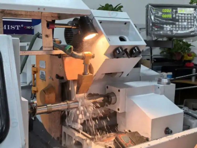
Inspection Determines Whether the Finished Part Matches the Specification
Machining is only complete when the finished geometry can be verified.
Ruizheng uses first-piece inspection, in-process inspection, and final inspection, supported by a constant-temperature inspection environment. Dimensional inspection reports can also be prepared when required.
For connecting rod machining tolerances, buyers should connect each critical drawing feature with an inspection method and inspection stage. This is especially useful for bore size, bore form, relative position, center distance, and functional face relationships.
A clear inspection plan makes sample approval more useful and reduces disputes after batch production begins.
How Should Buyers Source a Custom Connecting Rod Machining Partner?
The safest sourcing process begins with technical information, not a unit price.
Send the Drawing Before Asking for a Final Quote
A useful RFQ should include:
- 2D drawing;
- 3D model if available;
- material specification;
- blank condition;
- heat-treatment requirement;
- critical dimensions and geometric tolerances;
- inspection documentation;
- sample quantity;
- expected production quantity.
Ruizheng supports 2D/3D drawing evaluation, assembly tolerance suggestions, and quotation after drawing review for suitable projects.
This allows the machining route to be assessed against the actual component rather than estimated from a generic connecting rod description.
Validate Samples Before Releasing the Batch
A practical approval route is:
sample → dimensional review → assembly check → process adjustment where required → batch approval
This is particularly useful for billet projects because the main advantage of billet is design flexibility. If the geometry changes during development, sample approval provides a clear checkpoint before more parts enter production.
Use Ruizheng Precision Manufacturing Services for Drawing-Based Projects
Ruizheng is most relevant after the buyer has defined the material, blank route, geometry, and required condition.
Its role can include drawing review, machining-process planning, turning, milling, grinding, treatment coordination, dimensional inspection, and sample-to-batch support for non-standard mechanical parts.
That distinction matters. Ruizheng does not need to be positioned as a forging specialist for this topic. Its value is in helping turn a defined engineering drawing into a controlled, inspectable precision component.
For performance-engine projects, that final stage is just as important as deciding between billet and forged material routes.
Billet Connecting Rods can offer valuable design freedom for specialized, low-volume, or changing engine projects. Forged rods can make more sense for mature designs intended for repeat production. The better route depends on load conditions, material condition, heat treatment, section geometry, mass, production strategy, and final machining—not the manufacturing label alone.
If your project still has unresolved bore relationships, datum questions, heat-treatment requirements, or inspection points, prepare the drawing, material specification, target quantity, and required reports before making contact. That gives the machining team enough information to evaluate the process around the actual component requirements.
FAQ
Are Billet Connecting Rods Stronger Than Forged Rods?
Not automatically. Billet Connecting Rods provide greater freedom to revise geometry, while a properly designed forging may benefit from grain flow developed around the part shape. Actual performance depends on material condition, heat treatment, section geometry, component mass, surface condition, machining accuracy, and the loads created by the engine application.
When Is Billet a Better Fit for a Performance Engine?
Billet is often a practical route when the engine requires custom geometry, low production volume, prototype development, or repeated design revisions. If the design is already mature and repeat production is expected, forging may become more attractive. The final decision should also consider material, section geometry, mass, machining requirements, and inspection.
What Should I Send for a Connecting Rod Machining Project?
Send the 2D drawing, 3D model if available, specified material, blank condition, heat-treatment notes, critical tolerances, inspection requirements, sample quantity, and expected production quantity. These inputs allow the machining supplier to plan setups, finishing stages, and inspection around the functional features of the part.

