
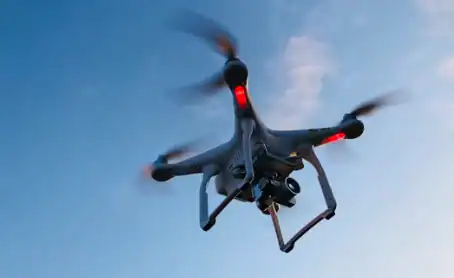
Unmanned aerial vehicles operating on liquid fuels subject their powertrains to continuous high-RPM stress, intense thermal loads, and strict weight restrictions. In these demanding conditions, proper optimization of Cylinder Bore Finish directly governs whether an engine achieves hundreds of hours of stable flight or suffers premature catastrophic failure. A microscopic flaw in sleeve wall surface geometry increases friction, causes blow-by, and raises operating temperatures beyond safe thresholds.
At Ruizheng, we specialize in high-precision component manufacturing, supporting global OEMs with custom shafts, cylinder sleeves, and non-standard engine parts designed for high-speed, high-load applications. Controlling micro-geometry and surface topographies is essential for prolonging powertrain life.
Why Is Cylinder Bore Finish Critical to UAV Engine Longevity?
Most small displacement two-stroke and four-stroke engines for UAVs run at constant high power output. As a result of wrong bore geometry, rapid mechanical wear leads to decreased performance of the engine.
Impact of Surface Micro-Roughness on Piston Ring Friction
The cylinder wall is more than just a smooth tube of metal. The bore surface needs an engineered cross-hatch topography. If the surface of the bore is too smooth then the lubricating oil will not be able to adhere to the surface of the cylinder wall. This would result in dry sliding contact between the piston ring and the cylinder sleeve. On the other hand, if the surface of the bore is too rough then the piston ring will be abrasive and wear the piston ring and the UAV engine cylinder as metallic debris is generated and accelerates overall wear.
Wear Mechanisms in High-RPM Fuel UAV Motors
Fuel-powered UAV motors encounter severe friction profiles due to elevated rotational speeds. Suboptimal cylinder bore finish leads to three main failure mechanisms:
- Scuffing and Galling: Direct metal-to-metal contact destroys the protective oil film under peak thermal loads.
- Gas Blow-By: Microscopic gaps along the cylinder wall allow high-pressure combustion gases to escape into the crankcase, dropping compression and degrading payload capacity.
- Thermal Overheating: Increased friction generates localized hot spots, warping sleeve geometry and locking moving parts.
Cost Consequences of Premature Cylinder Failure
Replacing damaged engine components during scheduled field maintenance or following mid-flight power loss drives up total operating costs. Unplanned downtime, frequent overhaul cycles, and potential airframe losses quickly outweigh initial component manufacturing savings. Shift your procurement evaluation from immediate part cost to long-term total cost of ownership.
How Does Precision Machining Control Bore Tolerances and Prevent Friction?
Controlling the dimensions, surface quality and metal composition during the machining process is critical to prevent mechanical wear.
Ultra-Precision Machining with 0.001mm Tolerance Control
By strictly dimensional measuring of all important dimensions of cylinder sleeves, piston slap and uneven wall friction can be prevented. Latest multi-axis CNC grinding and turning are processed in constant-temperature testing chambers with the highest processing accuracy of up to 0.001mm. In this way, perfectly round and straight cylinder sleeves are manufactured, and within the entire temperature range, with the exact surface roughness to create a stable lubrication film.
Advanced Material Selection and Heat Treatment Solutions
The material selection for a wear resistant part is critical for operation in extreme combustion environments. Lightweight aircraft parts are typically made from premium raw materials including alloy steel, stainless steel and titanium alloys. These parts are then subjected to custom heat treatment in order to achieve the required HRC hardness levels and subsequently harden the internal sleeve surface to withstand severe piston ring wear without sustaining any damage.
Concentricity Optimization for High-Speed and High-Load Scenarios
A refined cylinder wall provides little benefit if the axis is misaligned. Customized concentricity optimization for high-speed application scenarios ensures that multi-axis forces remain balanced. Correct concentricity eliminates lateral forces against the cylinder sleeve, extending overhaul intervals and reducing overall wear on high-rpm engine components.
Which CNC Components Best Solve Wear Issues for UAV Manufacturers?
Addressing friction and heat requires a holistic system approach, pairing engineered bore surfaces with high-precision internal components.
Precision UAV Engine Cylinder Bores and Sleeves
Custom cylinder sleeves engineered for small-capacity, high-output UAV powertrains provide superior wear resistance. Manufactured with engineered surface profiles, these custom Ruizheng CNC parts maintain reliable compression while keeping component weight to a minimum. Maintaining a consistent cylinder bore finish across production batches prevents premature wear and maintains cylinder sleeve tolerance across operating lifespans.
High-Performance UAV Crankshafts and Spindle Parts
Crankshaft alignment directly affects piston motion inside the cylinder sleeve. Precision-machined core high-precision shaft components suited for high-speed & high-load conditions feature low rotational runout and dynamic balance. Proper dynamic balancing prevents multi-axis vibration, preserving internal cylinder walls and stopping premature ring degradation.
Custom Non-Standard Precision Hardware and Accessories
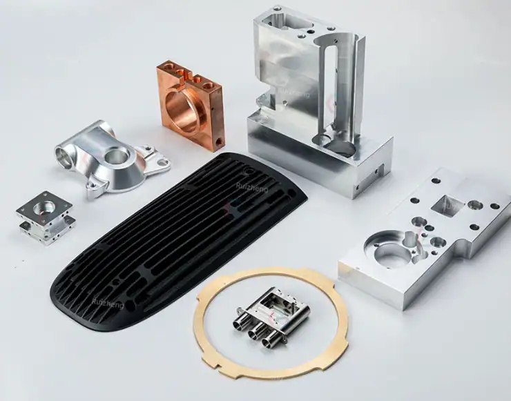
Every UAV powertrain design features unique mounting interfaces, cooling channels, and weight profiles. Producing components through 100% custom manufacturing based on client 2D/3D CAD drawings enables full compatibility across custom engine shaft machining, bearing seats, flanges, and non-standard engine fittings. Complete part compatibility eliminates localized stresses that cause cylinder deformation.
Why Partner with Ruizheng for Custom UAV Machining Services?
Achieving strict tolerances across prototype and production runs requires an established manufacturing system backed by comprehensive quality control.
ISO 9001 and SGS Certified Quality System
Our quality reliability is based on certified standards. Our processes are conducted in accordance with the ISO 9001 standards. The quality of our products is checked by means of SGS inspection reports. Our processes for manufacturing are set up in such a way that quality control is conducted on a constant basis. Every batch is checked for first-article inspection, in-process checks during the machining process and finally by means of a CMM test for dimensional verification in temperature controlled environments. The products are 100% compatible with the requirements of the European and American markets. They are also RoHS compliant.
Rapid 24-Hour Drawing Evaluation and Flexible Prototyping
Fast development cycles require swift technical communication. Engineering teams provide a complete 24-hour drawing evaluation and quotation upon receiving design files. Production timelines accommodate various project stages:
- Standard lead time: 20-30 days for general precision components.
- High-precision lead time: 40-60 days for complex, ultra-tight tolerance components.
- Trial production: Flexible small-batch prototyping support prior to full volume runs.
Global OEM Experience in High-Precision Manufacturing
Extensive experience in manufacturing precision CNC engine components for global industrial machinery and motor markets ensures seamless export workflows. Overseas logistics are streamlined with full export documentation and DDP (Delivered Duty Paid) shipping options available for international clients.
How Can UAV Manufacturers Start Optimizing Engine Components Today?
Upgrading engine reliability and extending flight hours begins with evaluating cylinder bore finish specs with your current manufacturing specifications and component tolerances.
Submitting 2D/3D CAD Files for Instant Evaluation
Engineers can submit 2D and 3D CAD drawings to evaluate geometry, material selection, and tolerance feasibility. Technical review helps identify potential assembly bottlenecks and cost-optimization opportunities before machining begins.
Ordering Low-Volume Trial Samples for Test Bench Verification
To verify performance on test benches, low-risk sample production runs allow engineers to test friction, heat dissipation, and wear rates under real operating conditions. Detailed inspection reports and defect-analysis video technical support assist during assembly and testing phases.
Utilizing Full Precision Machining Services
From turning and milling to precision grinding and specialized surface treatments, full machining services support complete powertrain manufacturing tailored to your exact flight requirements.
If you are experiencing cylinder bore wear, sealing failures, or need tailored tolerance recommendations for high-RPM UAV powertrains, our technical team is ready to review your project specs. To review drawing details or request a technical evaluation, contact our engineers directly to start optimizing your engine components.
FAQ
Q: What is the optimal cylinder bore finish for high-RPM fuel UAV engines?
A: An optimal cylinder bore finish is defined by a corresponding surface roughness (Ra and Rz values) which has to be matched to the piston ring material as well as to the lubrication oil’s viscosity. Instead of polishing, a specific micro-crosshatch-structure is ground into the cylinder bore in order to keep an oil film even under extreme thermal stress and to prevent any blow-by.
Q: How does cylinder bore finish affect UAV payload and flight endurance?
A: Suboptimal cylinder surface finishes generate excessive mechanical friction increasing fuel consumption to generate equivalent thrust. Engine efficiency is increased through reduction of internal friction by improving bore surface finish and dynamic balance. This increased efficiency results in improved payload capacity and extended time of flight.
Q: Can Ruizheng assist with tolerance and heat treatment recommendations for custom cylinder sleeves?
A: Yes, technical engineers provide assembly tolerance recommendations, material selection and custom heat treatment to maximize wear resistance of components made from materials such as alloy steel, stainless steel or titanium, based on client 2D/3D CAD drawings.

