
Tightening the connecting rod cap puts a big end under tension. The cap and rod body spread somewhat as the bolts in the cap are tightened to develop the necessary preload and to have the joint seats to spread. Thus the measurement of a bore with loose bolts on the cap will differ from the measurement of that same bore when the part is assembled to its specified dimensions. The change in measurement alone does not establish that a part is defective.
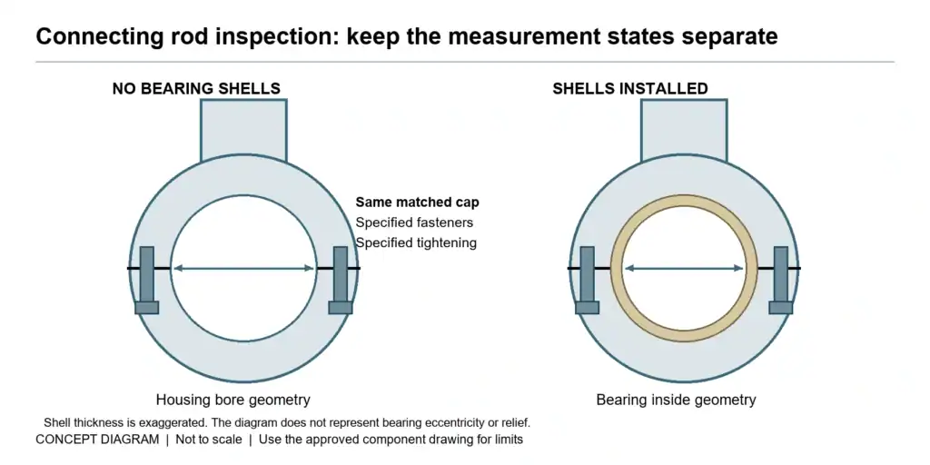
Prior to investigating any big-end bore distortion of connecting rod for automotive application, it is essential to establish what actual dimension has been measured: i.e. the housing bore without bearing shells or the measured dimension of the bearing inside. These are two quite different checks.
Why Does Tightening the Cap Change Bore Geometry?
Elastic Deformation Under Bolt Preload
As the rod bolt is tightened, it stretches and presses the rod cap onto the rod body. This force affects the stress distribution in the split housing and causes an elastic deformation. This deformation is determined by the design of the rod, the stiffness of the cap, the type of fasteners used and the contact conditions. The amount of deformation is not universal and a circular form is not necessarily changed in the same direction.
In evaluating whether a given assembly configuration is acceptable, the specified assembled configuration is to be used as a reference. A loose cap versus a fully tightened cap indicates a change in load, but neither configuration’s results are to be used as a reference to pass/d fail.
The same reasoning explains why bolt torque is not a direct measure for the clamping force. The friction in the threads as well as under the bolt head affects the relationship between torque and preload. A change of lubricant can affect the preload for the same torque value read off by a torque wrench.
The NASA Fastener Design Manual, which addresses friction and lubrication in torque-controlled assemblies, attempts to keep conditions within an assembly constant. However, this general information does not supersede specific fastener torque requirements for an automotive connecting rod.
Cap Location and Parting-Face Contact
The cap must return to its intended location and orientation. Depending on the design, locating features or matched fracture surfaces establish that position. The fasteners hold the joint together; they do not make an incorrectly matched cap fit correctly.
A little dirt or a raised burr can keep a section from fitting together. When tightened, a cap can seat unevenly and change the bore of the section. It’s very important to keep track of individual rod-and-cap pairs, even if they have the same nominal bore size. It’s tempting to swap caps of seemingly identical parts, but do not do this.
When Does Bore Shape Change Indicate a Problem?
Fasteners, Lubrication, and Tightening Conditions
First compare the assembly procedure as it was built in the factory with the procedure used for checking incoming parts. There should be information on the fasteners, the lubricants used, the sequence of assembly and the final torque setting. Just copying a torque value from another engine does not make it an acceptance test!
Some designs will list the part in torque-angle, others will list in bolt stretch or even torque method. Be sure to follow the specific instructions for the rod and fasteners. Don’t substitute a required method with a tool that you have available in the shop.
Check if the bore has to be checked according to the specified inspection for bolts which have been changed. The shape loaded by fasteners or the installation conditions can be different from previously experienced ones. Therefore, check the assembly instead of insisting on the same kind of correction machining for every change of bolts.
Cap Mismatch, Dirt, and Contact-Surface Damage
Verify identification marks and proper orientation prior to cleaning and reassembly. Examine all accessible locating and contact surfaces for damage. A part and assembled component appearing clean after disassembly may have raised marks caused by improper handling.
Fracture-split rods should be handled and repaired with the rod-and-cap assembly as specified by the manufacturer for that particular rod. Filing or grinding the joint surfaces to correct a joint that no longer seats is not necessarily an approved repair and should not be attempted. If a joint does not seat, do not continue to assemble the parts and attempt to correct the problem. Instead, determine why the joint will not seat and correct the problem prior to continuing.
Permanent Deformation and Prior Machining
Permanent changes in a bolt, such as caused by heat exposure, overload or previous repair, must be distinguished from repeatable elastic movement caused by tightening. One reading, even after repeated assembly under controlled conditions, does not prove serviceability.
Find out what happened to that part before it failed. Were the caps re-machined? Were the faces re-machined? Was the bore completed using the specified fasteners and completed in a proper manner using the specified assembly procedure? Find out what happened before attempting to fix it. There is no reason to re-size a bore until you find out what caused the discrepancy in the first place.
How Should the Big-End Bore Be Measured?
The Bare Housing Bore With the Cap Tightened
For the housing check, remove the bearing shells and assemble the correct cap using the prescribed fasteners and tightening conditions. Check the bare bore against the housing requirements on the drawing. Record the measurement method and assembly state with the result.
| Check | Assembly condition | What the result addresses |
| Housing bore | Correct cap tightened; no bearing shells | Housing size and specified form |
| Bearing inside diameter | Specified shells installed; cap tightened | Bearing bore under the specified assembly conditions |
| Oil clearance | Bearing bore and matching journal assessed by the prescribed method | Available clearance in the actual combination |
Avoid describing all three as “the big-end size.” That wording hides the information needed to interpret a rejection.
The Bearing Bore With Shells Installed
Once the shells are installed, their geometry becomes part of the measurement. Bearing shells can have designed eccentricity and relief near the parting line. The installed bearing bore should therefore be checked at the positions and by the method specified for that bearing arrangement.
A reading near the parting line cannot automatically be judged against a diameter requirement intended for another position. Nor should intentional bearing geometry be treated as proof that the bare rod housing is out of round.
Keep the measurements tied to the actual components. A housing report alone cannot establish oil clearance with an unspecified bearing shell and journal.
Measurements Across Angles and Axial Positions
Where the drawing calls for it, compare readings at several angular positions and along the bore width. This helps reveal variation that a single diameter reading misses. Keep the part clean and thermally stable, and use a suitable calibrated measurement setup.
A two-point bore gauge can screen changes in measured diameter. It cannot establish every form error, so it should not be treated as a substitute for a specified roundness measurement. Agree the inspection method before comparing results from different facilities.
What Should Buyers Specify for Repeatable Inspection?
The Drawing, Fastener Procedure, and Acceptance Limits
Our machining service is operated from customer supplied 2D drawings and 3D CAD models. Discussion of required assembly tolerances can also be undertaken. For the connecting-rod example, a description of the required finished-part and the relevant engine assembly procedure would be sought from the designer as part of the drawing evaluation process. Acceptance limits specific to the engine would be the responsibility of the designer.
The factory produces one-off mechanical parts of high precision and treats parts to heat when required. Please supply the required material condition and finished dimensions, and whether material reports and/or dimensional reports are required for the order. Such documents will be supplied on request and should identify the part and revision number to allow receiving inspection to check like with like.
We can work with a variety of materials including alloy steel, stainless steel and titanium alloy, depending on customer requirement. The workshop is equipped with lathes, milling machines and grinders as well as fully automated loading and unloading of components. This is general machining capability and does not imply that some arbitrary rod design has been subjected to engine test.
Sample Validation and Inspection Records
Support of samples and small batch production for trial prior to placing larger orders. Our quality control workflow encompasses first piece inspection, ongoing production checks and final shipment inspection. In addition, dimensional checks are conducted in a temperature controlled inspection room. Assembly tolerance advice is also given during project review.
Use the sample stage to agree any differences between supplier’s measurement method and your receiving method. Get supplier to record the assembled state and dimensions and at the custom stage agree the production details prior to manufacture and then discuss any assembly points during the production details review.
Where a quality issue occurs, our after-sales support includes defect analysis and technical communication, including video discussion when useful. Send the part identification, inspection results and assembly procedure together. That gives the review something specific to investigate and avoids treating every unexpected reading as the same machining fault.
This order policy allows returns or exchanges in case of defects. It does not allow returns of custom products unless there are defects not related to the customizations and these have been detailed before production started. This company also provides information on use and on how to assemble items. The stated lead time for ordinary parts is 20–30 working days. For high-end precision parts the lead time is 40–60 working days. The actual lead time for a given part drawing and quantity can however always be confirmed first.
Discuss Your Connecting Rod Drawing With Ruizheng
Ruizheng provides drawing-based CNC machining services for non-standard mechanical parts. Send your automotive connecting-rod drawing for a feasibility review, including material condition, fastener instructions, quantity and required inspection records. The company supports drawing evaluation, sample production and discussion of assembly tolerances before batch release.
For the wider set of features to specify, see our guide to automotive connecting rod machining. If the current problem is an assembly-dependent bore reading, send the drawing and measurement conditions together so the review starts with the correct inspection state.
FAQ
Should the Big-End Bore Be Checked With the Cap Loose?
A loose-cap reading cannot replace acceptance testing in the specified assembled condition. Use the correct cap, fasteners and tightening procedure. A free-state measurement is useful only when the drawing or investigation specifically calls for it.
Can Changing Rod Bolts Require Another Bore Check?
Yes. A change in fasteners or tightening conditions can alter preload and loaded geometry. Follow the applicable rod and bolt instructions, then verify the bore as required. Do not assume the old report applies unchanged.
Does a Diameter Check Prove the Bore Is Round?
No. One diameter reading gives limited information. Readings at multiple positions help screen variation, but a specified roundness requirement needs an appropriate form-measurement method. Keep bearing-shell geometry separate from bare-housing roundness when interpreting the result.

